The Metal Coil Slitting Machine, Part by Part
A slitting machine cuts a wide master coil of metal lengthwise into several narrower strips. Rotating arbors carry pairs of rotary knives that shear the strip as it feeds through, and precision spacers between the knives set each width.
Everything here is about metal: steel, stainless, aluminium and copper coil, on a line with an uncoiler at one end and a recoiler at the other. Paper, film and plastics slitting are different trades with different tooling, and this page will not help with them.
The parts, the process, line speed and accuracy by gauge, knife clearance, installation, and what to check before buying.
Last updated: September 2026
Performance Is Defined by Tooling Accuracy
How slitter knives, spacers, and rolls control cut quality and repeatability.
What is a slitting machine?
A slitting machine is a coil processing line that cuts a wide master coil into narrower strips. It feeds the strip through two rotating arbors fitted with rotary knives and spacers, shears it lengthwise to set widths, and rewinds each strip into its own tight coil on a recoiler.
A slitting machine operates as a high-precision production line, transforming master coils into narrower strips. The integrity of the final product relies on the rigidity of the arbor and the setup of key tooling components.
- Rotary Knives
- Precision Spacers
- Stripper Rings & Rolls
*Proper setup minimizes edge wave and burr formation in recoiled strips.
Longitudinal Cutting
Shearing metal lengthwise with rotary knives under controlled tension.
Recoil Tension
Maintaining tight, uniform coils for downstream stamping or roll forming.
Arbor Rigidity
Minimizing deflection for burr-free edges. The foundation of accuracy lies in shaft stability.
What is a slitter?
On the shop floor, slitter is used two ways. It can mean the whole machine, the line that cuts coil into strips. It can also mean the tooling assembly itself, the arbor loaded with knives and spacers. Context tells you which: running the slitter versus building the slitter. A setup crew saying the slitter needs new knives means the tooling. A plant manager saying the slitter is down means the line.
Slitter machine and slitting machine are the same thing. Both differ from a cut to length line, which cuts across the width into flat sheets instead of along it, and from a plain rewinder, which respools a coil without cutting it into multiple strips. If you are choosing between the first two, there is a section below on which one your order actually needs.
Types of Slitting Lines and Slitting Systems
Service centres and tube mills specify a line by four numbers: gauge range, maximum coil width, maximum coil weight, and how many cuts it has to make in one pass. Those four decide everything downstream, tooling included.
Three configurations cover most of the market:
- Light-gauge lines run thin material, roughly 0.15 mm to 2.0 mm, at high speed. They use narrow arbors, thin knives, and rubber-bonded spacers to hold many close strips. Coil weights are usually under 10 tons and cut counts can run past 20 strips in a pass.
- Heavy-gauge lines cut roughly 2 mm to 12 mm and above. They use large-diameter arbors, thick knives, and metal spacers, because rubber compresses too much under the higher separating forces. Expect fewer, wider strips per pass and much larger coil weights.
- Precision and high-speed systems target tight width tolerance, often plus or minus 0.05 mm, on thin stock for stamping, tube, and lamination work. They add close-tolerance tooling, overarm separators, and tension stands so strips do not wander between the head and the recoiler.
Within any of these, the slitter head is either a single-arbor design (knives and spacers built directly on one shaft pair) or a cassette design, where a pre-built arbor set is swapped in and out to cut changeover time. The system you run decides which tooling you buy and how you set clearance, so treat the line, not just the knives, as the unit of decision. For a component-by-component breakdown of what rides on the arbors, see the slitting line tooling guide.
The Slitting Process: Coil to Recoiler
Uncoiler
Master Coil FeedSlitter Head
Critical Tooling ZoneRecoiler
Finished Strips*Schematic representation of a standard precision slitting line. Tooling accuracy at the Slitter Head determines the quality of the entire output.
Slitting Machine Parts, Station by Station
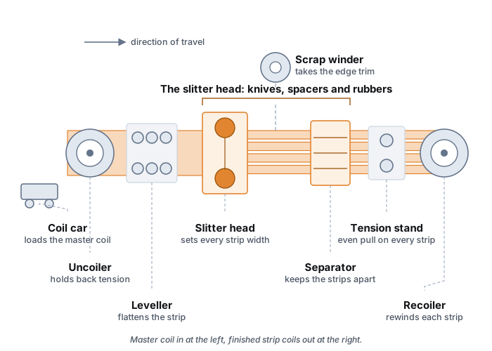
Coil car. Lifts the master coil off the floor and onto the uncoiler mandrel. Unglamorous, and the first thing to look at when changeover time is the complaint, because a line whose coils are walked on with a crane loses more time here than anywhere on the head.
Uncoiler (payoff). The master coil sits on a mandrel that expands to grip the coil bore. A drag brake or motorized payoff holds back-tension so the strip does not slack as it feeds. If the uncoiler cannot keep the coil centered, the strip walks sideways into the knives and width drifts across the coil length.
Slitter head. This is the working zone. Two parallel arbors carry the rotary knives and the spacers that set each strip width. The upper and lower knives overlap by a set depth and sit apart by a set horizontal clearance. Everything that decides width tolerance and edge quality happens here, which is why the head is the part you build with the most care.
Tensioning (looping pit or tension stand). After the cut, the strips need even pull to stay flat and to wind tight. Light-gauge lines use a looping pit that lets the strips hang in a controlled loop between the head and recoiler. Heavier or faster lines use a driven tension stand with pads or rolls. Uneven tension across the strips is a common cause of loose wraps, telescoping, and edge damage on the recoiler.
Recoiler (rewind). Each strip is rebuilt into its own coil on a segmented or expanding mandrel, usually with separator discs or an overarm to keep the strips from climbing over each other. Tension, wrap tightness, and separation quality here decide whether the finished coils ship clean or get rejected for edge wave and loose wraps.
How a Slitting Cut Is Actually Made
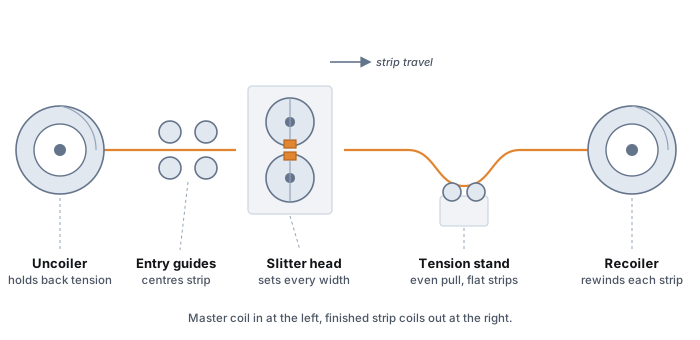
Slitting is not sawing and it is not shearing in a single plane. It is a controlled fracture. The upper and lower knives do not meet; they pass each other with a small side gap (horizontal clearance) and a small overlap (penetration). As the coil feeds through, each pair of knives presses into the strip from both faces, starts a crack, and the metal tears cleanly along that crack. Get the geometry right and the edge looks sheared and bright. Get it wrong and the same machine makes burrs, slivers, or a rough torn band.
Two settings control the result. Clearance is how far apart the two knife faces sit sideways, given as a percentage of gauge per side. Run it tight and the knives rub, wear quickly and pull camber into the strip; run it loose and the two cracks never meet, which is where burr and edge droop come from. Penetration, or overlap, is how far the upper knife reaches past the lower one. Thin ductile metal wants more of it to start the fracture, thick hard metal wants less. Those two numbers, a sharp edge and a shaft that is not flexing are the whole of edge quality.
This is also why the same coil can run perfectly one day and poorly the next with no change in material. A knife that has lost its edge, a spacer stack that has drifted a few hundredths, or a shaft that has picked up runout will all change the effective clearance at the cut. Slitting quality is a system property, not a single setting, which is why disciplined setup and tooling records matter as much as the numbers.
Working out spacer widths and knife clearance by hand for a new job? The free calculator does the arithmetic for each pocket in seconds.
Open the free calculatorPrecision in Every Cut
In high-speed slitting, tolerance stacking is the enemy of quality. Any deviation across a set of spacers can result in cumulative error, leading to significant burr generation and knife chipping. Our tooling is ground to rigorous industrial standards to ensure your setup time is reduced and your edge quality is consistent from the first cut to the last.
Defect Analysis & Tooling Causes
| Defect Type | Visual Symptom | Likely Tooling Cause |
|---|---|---|
| Excessive Burr | Rough edge pointing up/down | Incorrect horizontal clearance setting or dull knife edges. |
| Camber (Snake) | Strip curving left or right | Uneven stripper ring pressure or misaligned arbor shafts. |
| Knife Marks | Scoring on strip surface | Stripper rings are wrong diameter (too small) or damaged. |
| Edge Wave | Rippled edges on strip | Excessive overlap setting causing metal deformation. |
Arbor and Slitter Shaft Specifications
The arbor, or slitter shaft, is what the whole tooling pack is built onto. Its job is to keep every knife where you put it while the cut tries to shove the pack apart. Four numbers describe one, and none of them is a brand name.
- Diameter. Stiffness, essentially. It also sets the bore that all your tooling has to match, which makes it the one number here you cannot revisit later without replacing the lot. Ranges by gauge class are in the tooling guide.
- Deflection and runout. Under separating force the shaft bows slightly. Good lines hold total indicated runout to a few hundredths of a millimeter. Excess deflection shows up as width that grows toward the center strips and as burrs that appear only on the widest cuts.
- Keyway or keyless drive. A keyed shaft transmits torque through a key and keyway; a keyless (hydraulic or shrink) shaft grips the tooling all the way around. Keyless shafts hold position better on high-cut-count precision work but cost more and are slower to service.
- Overhung length. The distance from the outboard bearing to the last knife. The longer the overhang, the more the shaft flexes. Keeping the heaviest cuts nearest the bearing, and the largest spacer nearest each knife, is how you fight that flex during a build.
Shafts are consumable, not permanent. Runout belongs on the maintenance schedule alongside the knives, because a shaft that has drifted out of true cannot be compensated for anywhere else on the line. The tooling guide covers sourcing and replacement.
For the full component breakdown of what rides on the arbor, the tooling guide covers slitter shafts, slitter spacers, ejector rings, and separator discs in detail.
Knife Clearance Quick Reference
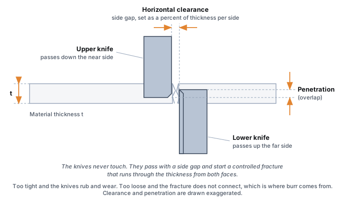
Clearance is the side gap left between the upper and lower knife faces, given as a percentage of material thickness per side. These percentages are shorthand for typical tensile bands rather than properties of the metal itself, so the same alloy in a hard temper and a soft temper will not take the same figure. Treat them as a starting point and confirm with a test cut. For a fuller breakdown by tensile band, see the slitter knife clearance chart published by Maxwell Slitter Industries.
On a standard line the arbors are fixed axially, so this gap is not something the operator dials in at the machine. It is whatever the tooling stack on the arbor makes it, which is why the clearance number and the spacer pack are the same decision.
| Material | Clearance (% per side) | Notes |
|---|---|---|
| Cold rolled steel | 8% | The baseline most service centres work from |
| Hot rolled steel | 10% | Heavier and less uniform than CR, so it takes a wider gap |
| Galvanised and Galvalume | 10 to 11% | Pre-painted sits at the top of the range to protect the coating |
| Stainless steel | 10 to 14% | 430 at the bottom, 304 in the middle, 316 at the top |
| Electrical steel (CRGO and CRNGO) | 6 to 7% | Thin and abrasive; the burr limit usually decides this, not the chart |
| Aluminium | 5 to 6% | 1xxx and 3xxx at the bottom, 5xxx and 6xxx at the top |
| Copper and brass | 6 to 7% | Ductile, so the gap stays tight or the edge tears rather than shears |
| Tinplate | 6% | Treated as CQ steel for clearance |
| HSLA and advanced high strength steel | 14 to 25% | Rises steeply with tensile; verify on a test cut before a production run. Figure from the Maxwell clearance chart, not from the solver, which carries no AHSS baseline |
Worked clearance by gauge (carbon steel at 9 percent per side)
Clearance is set by gauge, not just by material family. Multiply the material thickness by the percentage from the table above. These are carbon steel examples at a mid-range 9 percent per side. Thinner gauge needs a proportionally smaller absolute gap, which is why thin stock is far less forgiving of a worn shaft.
| Gauge (thickness) | Clearance per side | Practical note |
|---|---|---|
| 0.30 mm (about 28 ga) | 0.027 mm | Very tight; needs low shaft runout and sharp knives |
| 0.60 mm (about 24 ga) | 0.054 mm | Common light-gauge setting |
| 1.00 mm (about 20 ga) | 0.090 mm | Forgiving baseline for setup training |
| 2.00 mm (about 14 ga) | 0.180 mm | Heavier knives; watch separating force |
| 3.00 mm (about 11 ga) | 0.270 mm | Heavy-gauge; metal spacers, large arbor |
For a per pocket spacer and clearance calculation from your own numbers, use the free slitting calculator. For edge-quality troubleshooting, see the slitting problems guide. For high-strength grades, clearance runs wider; see slitting advanced high-strength steel.
Arbor Setup Best Practices
A well-assembled arbor is the foundation of every good slit. Follow these principles to minimize width variation and edge defects:
- Clean everything, arbor shaft, spacers, and knives must be free of debris before loading
- Fewest spacers per pocket, since every extra part is one more tolerance stacked on the last
- Largest spacer nearest the knife, maximizes rigidity against cutting forces
- Verify with test cut, measure strip widths at 3 points and inspect edge quality before production
- Consider shimless operation, fraction kit spacers deliver tighter tolerances than plastic shims
For a whole setup on video, from an empty account to a printed sheet, see the five minute walkthrough. For a complete written walkthrough with load sequences and common mistakes, read our step-by-step arbor setup guide. Need automated spacer selection from your actual inventory? Try OptiStack Pro free for 14 days.
Slitting line, slitter head, or cut to length line
Three terms that get used interchangeably and should not be.
- Slitter head. The cutting station itself: the two arbors and the knives, spacers and rubbers built onto them. When someone says the slitter needs rebuilding, this is usually what they mean.
- Slitting line. The whole line around that head, from uncoiler through tension and separation to recoiler. It changes the WIDTH of a coil and the output is still coil.
- Cut to length line. Cuts ACROSS the width into flat sheets or blanks. It changes length, and the output is a stack, not a coil.
The practical version: if the customer ordered coil, you need a slitting line. If they ordered sheet, you need a cut to length line. Plenty of service centres run both, and some lines combine them, but they are different machines solving different orders and the tooling does not transfer.
Cutting accuracy, and where width tolerance actually comes from
Strip width tolerance is not a property of the machine. It is the sum of the tooling stack that produced it, and that is good news, because a stack is something you can measure and control.
Every strip width is the distance between two knife faces, and that distance is built from real parts with real tolerances: knife thickness, every spacer in the pocket, and the bore fit of each of them on the arbor. Ten parts each held to a few microns still add up, and they add up in whichever direction the errors happen to point. This is why a line that holds width beautifully on a four-strip job can miss on a twenty-strip job with the same tooling.
What moves the number, in the order it usually matters:
- Spacer tolerance class. The single biggest lever, and the one that is decided at purchase rather than at setup.
- Knife thickness after regrind. A reground knife is not its nominal thickness any more. If the stack is calculated from nominal, the error is built in before the first coil.
- Arbor runout. Moves the cut position through the whole job.
- Arithmetic. The one that is free to fix.
If you want the accumulation worked through with your own numbers rather than described, the slitting calculator shows the pocket arithmetic for a given coil width and slit pattern, and flags the pattern your inventory cannot actually build.
How fast a slitting line runs
Line speed is set by the slowest thing on the line, and that is almost never the slitter head. It is usually the recoiler tension control, the separator, or an operator who needs to see the strip.
What actually limits it, roughly in the order it bites:
- Gauge and strip count. More strips means more edges to keep flat and more tension to distribute. A heavy gauge in a few wide strips runs faster than a light gauge in twenty narrow ones.
- Tension control. Strips of slightly different length off the same coil have to be taken up somewhere. The looping pit or tension stand is what lets you go faster.
- Edge quality target. Speed and burr are related through heat. If the clearance is marginal, speed makes the burr worse, which is why the honest answer to a burr problem is often to slow down until the clearance is verified.
- Coil changes. On short coils, threading time dominates and top speed barely matters to the tonnage figure.
Published speed figures from machine builders are top speeds on favourable material, and comparing them between builders is not very useful. The number worth knowing is your own throughput on the job mix you actually run, which is coil weight divided by the time from thread to thread. The coil calculator gives you the weight and the strip length, and the run time at a speed you type in.
Installing and commissioning a slitting line
Installation is mostly foundation and alignment work, and the mistakes made here are the ones you cannot fix later with tooling.
Foundation. The uncoiler, slitter head and recoiler need a floor that will not move relative to each other. A coil car running between them wants a level track. Grouting and levelling is slow and nobody enjoys it, but a head that settles a fraction of a degree out of square pulls camber into every strip afterwards, and no clearance setting compensates for it.
Alignment. Everything is squared to the pass line, not to the building. The uncoiler mandrel, the entry guides, the arbors and the recoiler mandrel share one centreline. Check it with a taut wire or a laser before anything is bolted down, and check it again after grouting has cured.
Arbor runout. Dial indicate both arbors before the first coil and record what you find. This is your baseline: when cut quality drifts a year later, the question is always whether the shaft has moved, and without a commissioning figure it cannot be answered. Runout above roughly 0.05 mm is a problem to solve now rather than to work around.
Commissioning cuts. Run the material you will actually run, not the softest thing to hand. Start mid-range on gauge, measure strip widths across the full set rather than one strip, and check both edges. The first setup is also the moment to record the arbor lengths, clamp reserves and usable width that every future setup is calculated from. Those go into the machine profile once and are reused on every job after.
What a slitting line costs to run
Machine prices vary so widely by width, gauge, tonnage and builder that any figure quoted here would be a guess, so this section covers the running costs instead, which are the ones that are actually comparable between shops.
Tooling is the recurring cost that surprises people. A full arbor set is knives, spacers, separator discs and rubbers for both arbors, and it is bought once and reground for years. The cost that matters is not the purchase but the cost per ton of slit material, which means tracking how many tons an edge gives you before it needs regrinding, by material. Nobody can hand you that number: it depends on your gauge, your tensile, your speed and your clearance discipline.
Regrinding. Every pass takes diameter off the knife, and once the diameter is gone the knife can no longer reach far enough past its partner to cut your gauge. So the outside diameter you order decides how many regrinds you get out of it, which makes this a purchasing decision dressed up as a maintenance one. The specification side of this is in the blade specification guide.
Scrap and rework. Usually the largest of the three and the least tracked. Edge trim is planned scrap and predictable. Off-width strip, burr rejects and re-runs are not, and they come from setup rather than from the machine.
Changeover time. A line that is being rebuilt is not cutting. Whether that matters depends entirely on how many changeovers you run a week, which is why an hourly line rate is the number to have before any of the rest of this can be costed.
Operator Maintenance Checklist
Daily
- ✓ Inspect knife edges for chips or cracks
- ✓ Clean arbor shafts of debris and metal particles
- ✓ Check stripper ring condition and pressure
- ✓ Verify clamp torque after first cut
Weekly
- ✓ Measure spacer widths for wear tolerance
- ✓ Inspect rubber spacers for compression/cracking
- ✓ Lubricate arbor bearings per OEM spec
- ✓ Check separator disc flatness
Monthly
- ✓ Full spacer inventory audit and re-measurement
- ✓ Verify arbor shaft runout with dial indicator
- ✓ Inspect keyways for wear or deformation
- ✓ Review knife regrind log and schedule
After Regrind
- ✓ Verify new knife OD and bore dimensions
- ✓ Recalculate clearance with updated knife geometry
- ✓ Run test cut and inspect edge quality
- ✓ Update knife inventory in OptiStack
Want to reduce changeover time between maintenance intervals? where the minutes in a changeover actually go.
Common Slitting Machine Buying Mistakes
A slitting line is a ten to twenty year purchase, and the tooling and consumables cost more over that life than the machine did. Most regret traces back to four decisions made before the order.
- Buying for peak gauge only. A line sized for the heaviest coil you might run is clumsy on the thin, high cut count work that actually pays. Size it for the week you usually have, not the job you have once a quarter.
- Not checking tooling supply. Knives, spacers and shafts are what you touch every shift. Confirm that precision spacers, fraction kits and replacement arbors are available and hold tolerance before you commit.
- Underspecifying the arbor. A shaft that flexes will never hold width on the centre strips. Diameter is cheaper at the order than it is for the next decade.
- Treating setup as tribal knowledge. If one veteran is the only person who can build a clean arbor, every changeover depends on that person being in.
Choosing between machines and builders is a different job from running one, and Maxwell cover it properly in their guide to buying a slitting line. For the tooling questions, see blade specification and the slitting line tooling lineup.
Build every arbor from the stock you already have
OptiStack Pro computes a buildable spacer stack and knife layout for each pocket from your real inventory, so setup does not depend on one veteran. Start a free 14 day trial, no credit card.
Start free trialFrequently Asked Questions
What is a slitting machine used for?
How does a slitting machine work?
What determines cut quality in a slitting machine?
What should I check before buying a slitting machine?
What causes burrs and edge defects in slitting operations?
Can one slitting machine handle different materials and thicknesses?
How often should slitter knives be replaced or reground?
How many knives can a slitting arbor hold?
Related Slitting Resources
Technical guides by language
- Español: Línea de corte longitudinal
- Italiano: Linea di taglio longitudinale
- Deutsch: Längsteilanlage
- Русский: Линия продольной резки
- Português: Linha de corte longitudinal
- Türkçe: Rulo sac dilme hattı